A Comprehensive Guide to Automotive Electromagnetic Compatibility Standards and Validation Methodologies
Introduction to Electromagnetic Compatibility in the Automotive Domain
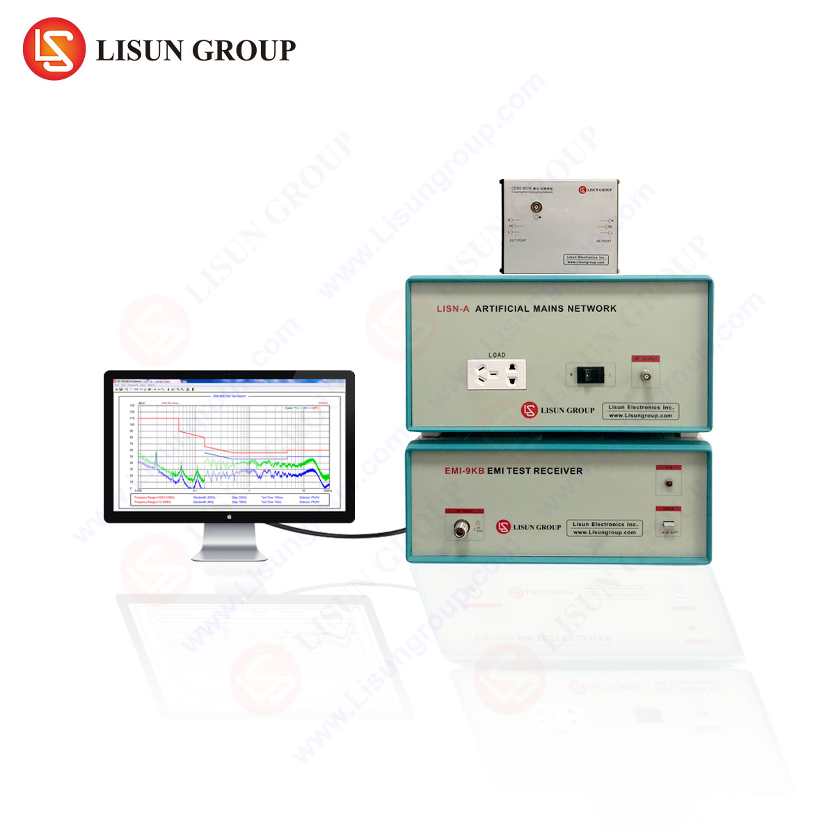
The modern automobile represents one of the most complex electronic systems in mass production, integrating a dense ecosystem of electronic control units (ECUs), high-speed communication networks (e.g., CAN FD, Automotive Ethernet), wireless connectivity modules (e.g., GPS, 5G, V2X), and high-power motor drives for electrification. This convergence of technologies operates within a harsh electromagnetic environment, making Electromagnetic Compatibility (EMC) a critical discipline for functional safety, reliability, and regulatory compliance. Automotive EMC encompasses two fundamental aspects: the vehicle’s immunity to external electromagnetic disturbances and its control of electromagnetic emissions that could interfere with external systems or its own internal electronics. A rigorous framework of international standards, primarily from the International Organization for Standardization (ISO) and the Society of Automotive Engineers (SAE), governs the validation of these characteristics. This guide details the core principles of automotive EMC standards, the testing methodologies employed, and the instrumental role of precision measurement equipment, such as the LISUN EMI-9KB EMI Receiver, in ensuring compliance.
Fundamental Principles of Automotive Electromagnetic Emissions and Immunity
Electromagnetic Interference (EMI) in the automotive context is categorized by its propagation mechanism: conducted or radiated. Conducted emissions refer to unwanted high-frequency noise currents traveling along power supply lines and communication cables. Radiated emissions are electromagnetic fields propagating through the air, emanating from the vehicle or its components. Conversely, immunity testing evaluates a device’s ability to operate correctly when subjected to such disturbances. Key phenomena include:
- Broadband Noise: Typically generated by switching power converters and electric motor drives, characterized by a continuous spectrum.
- Narrowband Noise: Often originating from clock oscillators and microprocessors, appearing as distinct spectral lines.
- Transient Disturbances: High-energy, short-duration pulses such as those from load dump (a sudden disconnection of the battery while the alternator is generating current), electrostatic discharge (ESD), and inductive load switching.
The proliferation of power electronics in Electric Vehicles (EVs) and Hybrid Electric Vehicles (HEVs) introduces significant EMC challenges. The high dv/dt (rate of voltage change) and di/dt (rate of current change) in traction inverters and DC-DC converters are potent sources of both conducted and radiated emissions, necessitating advanced filtering and shielding strategies.
Global Regulatory and OEM-Specific EMC Standards Framework
Compliance with regional regulations and stringent Original Equipment Manufacturer (OEM) requirements is mandatory for market access. The regulatory landscape is built upon a foundation of international standards, which are often adopted and extended by individual automotive manufacturers.
Key International Standards:
- CISPR 12 & CISPR 25: Published by the International Special Committee on Radio Interference, these are the cornerstone standards for vehicle and component-level EMC. CISPR 12 specifies limits and methods for the protection of off-board receivers from vehicles, boats, and internal combustion engines. CISPR 25 establishes limits and procedures for the protection of on-board receivers, defining test methods for both conducted and radiated emissions within the vehicle.
- ISO 11452 Series (Component Immunity): This multi-part standard details methods for testing component immunity to radiated electromagnetic energy. Key parts include ISO 11452-2 (ALSE – Absorber Lined Shielded Enclosure method), ISO 11452-4 (BCI – Bulk Current Injection), and ISO 11452-5 (Stripline Method).
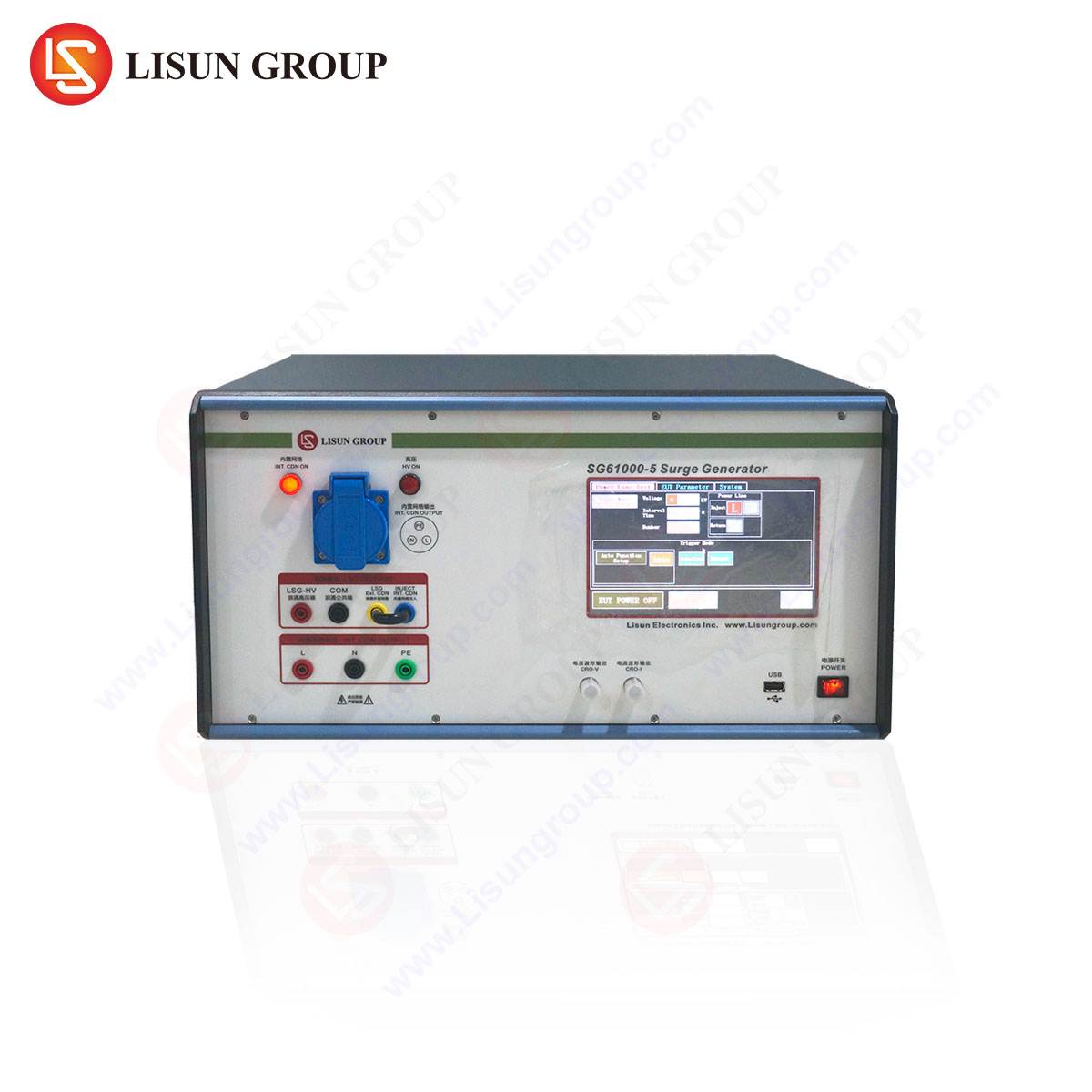
- ISO 7637 Series (Electrical Transients): This standard addresses immunity to electrical transients conducted along supply and signal lines, simulating real-world scenarios like load dump and switching of inductive loads.
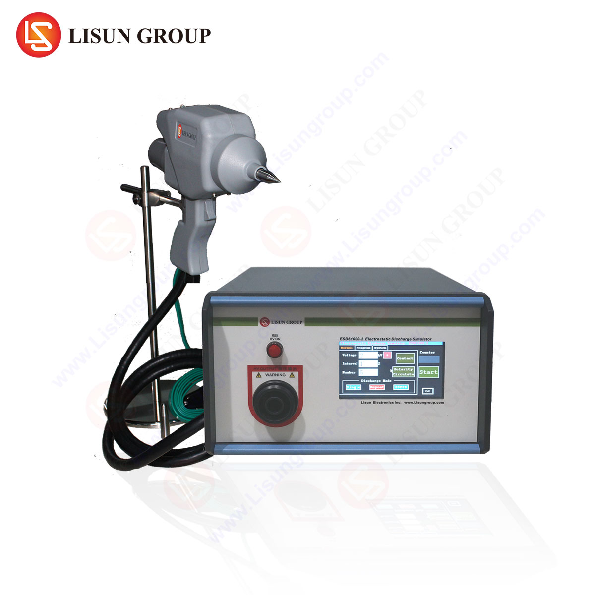
- ISO 10605 (Electrostatic Discharge): Specifies test methods for evaluating a component’s resilience to ESD events that may occur during manufacturing or user interaction.
OEMs, such as Volkswagen, Ford, General Motors, and Toyota, publish their own corporate EMC specifications (e.g., VW TL 81000, GMW 3097, Ford EMC-CS-2009). These documents typically impose more rigorous limits and additional test cases beyond the international standards to ensure robustness for their specific vehicle architectures.
Advanced EMC Testing Methodologies for Vehicle Subsystems
EMC validation is a multi-layered process, applied from the individual component to the complete vehicle level.
Component-Level Testing: This is the first line of defense, where individual ECUs, sensors, and modules are tested in a controlled laboratory environment. An EMI receiver is central to this phase for emissions profiling. For example, a power window motor’s controller would be tested for both its radiated emissions and its immunity to BCI, ensuring it does not malfunction when subjected to induced RF currents on its harness.
System-Level Testing: This involves testing interconnected subsystems, such as an infotainment head unit connected to a digital audio amplifier and a telematics module. The focus is on identifying interoperability issues and cumulative emissions that may not be apparent in isolated component tests.
Whole-Vehicle Testing: The final validation stage occurs in a semi-anechoic chamber or an open area test site (OATS). The entire vehicle is subjected to radiated immunity tests, where high-power antennas broadcast electromagnetic fields across a wide frequency range (e.g., 20 MHz to 18 GHz) to simulate external transmitters. Simultaneously, its radiated emissions are measured to ensure it does not exceed limits that would interfere with external communication systems or its own sensitive receivers.
The Role of Precision EMI Receivers in Automotive Compliance Testing
The accuracy and repeatability of EMC measurements are paramount, as they form the basis for compliance certification. EMI Receivers, as opposed to spectrum analyzers, are specifically designed and calibrated for this purpose, adhering to CISPR 16-1-1 requirements for detector types (Peak, Quasi-Peak, Average), bandwidths, and measurement uncertainty.
LISUN EMI-9KB EMI Receiver: A Benchmark for Automotive EMC Validation
The LISUN EMI-9KB is a fully compliant EMI test receiver engineered to meet the rigorous demands of automotive EMC testing laboratories. Its design and specifications align directly with the requirements of CISPR, ISO, and major OEM standards.
Specifications and Testing Principles:
- Frequency Range: The EMI-9KB covers a frequency range from 9 kHz to 30 MHz for conducted emissions and, when coupled with appropriate preamplifiers and antennas, extends to 1 GHz or higher for radiated emissions, covering the entire spectrum of concern for automotive applications.
- Detectors and Bandwidths: It incorporates all mandatory detectors—Peak, Quasi-Peak (QP), Average, and RMS-Average—with CISPR-standard 200 Hz, 9 kHz, and 120 kHz bandwidths. The QP detector is particularly critical, as it weighs emissions based on their repetition rate and amplitude, reflecting the human ear’s annoyance to impulsive radio interference, a core principle of CISPR standards.
- Dynamic Range and Preamplifier: With a high dynamic range and an integrated, low-noise preamplifier, the EMI-9KB can accurately measure both low-level emissions from sensitive communication equipment and high-level noise from power electronics without overloading.
- Automated Measurement Sequences: The receiver supports fully automated testing, including frequency scanning, limit line comparison, and data logging. This is essential for executing lengthy immunity and emissions scans as prescribed by standards like CISPR 25, which require measurements at multiple antenna polarizations and device-under-test (DUT) operating modes.
Industry Use Cases and Application Examples:
- Power Equipment & Electric Vehicles: Validating the conducted emissions on the high-voltage DC bus of an EV’s traction inverter to ensure compliance with CISPR 25 Class 5 limits.
- Communication Transmission: Testing the electromagnetic emissions from a Vehicle-to-Everything (V2X) transceiver module to prevent self-interference with other critical on-board receivers like GPS.
- Household Appliances & Power Tools: While not automotive, the principles are identical. Testing a 12V DC air compressor designed for automotive use for both its radiated emissions and its immunity to transients on the vehicle’s power supply (ISO 7637-2).
- Instrumentation: The EMI-9KB itself, as a precision instrument, must be designed to have negligible self-emissions to avoid contaminating the measurement environment.
Competitive Advantages in the Automotive Sector:
The LISUN EMI-9KB offers distinct advantages for automotive EMC labs. Its robust construction ensures stability during long-duration automated tests. The intuitive software interface reduces setup time and potential for operator error. Furthermore, its calibration traceability to national metrology institutes provides the measurement integrity required for submissions to major OEMs. Compared to more expensive alternatives, the EMI-9KB delivers full compliance with a lower total cost of ownership, making it an optimal solution for both tier-1 suppliers and OEM R&D departments.
Cross-Industry EMC Considerations and Synergies
The principles and technologies of automotive EMC are highly transferable. A component designed for an automotive environment must often meet EMC robustness levels that exceed those of other industries.
- Medical Devices: An automotive-grade ECU has a similar immunity requirement to a portable medical device used in an ambulance, both needing to function reliably in the presence of strong RF fields.
- Rail Transit & Aerospace: These sectors share the automotive focus on functional safety and operate in even more extreme EM environments. Testing methodologies for conducted transients (similar to ISO 7637) are common.
- Information Technology Equipment: While governed by CISPR 32, the underlying measurement science using an EMI receiver like the EMI-9KB is consistent, differing primarily in test setups and limit values.
Future Trends and Evolving Challenges in Automotive EMC
The trajectory of automotive innovation ensures that EMC will remain a dynamic and critical field. Key future challenges include:
- Higher-Frequency Demands: The adoption of 5G, millimeter-wave RADAR (77 GHz), and higher-speed Automotive Ethernet will push EMC validation into frequency ranges beyond 10 GHz.
- Electrification and High-Power Electronics: The shift to 800V and higher architectures in EVs will exacerbate challenges related to common-mode currents and magnetic field coupling, requiring more sophisticated simulation and measurement techniques.
- Automated Driving Systems (ADS): The functional safety (ISO 26262) of ADS is intrinsically linked to EMC. A transient-induced malfunction in a sensor fusion ECU could have severe consequences, driving the need for more stringent immunity testing and fault-tolerant design.
FAQ Section
Q1: What is the critical difference between using an EMI Receiver like the EMI-9KB and a standard spectrum analyzer for compliance testing?
A1: EMI Receivers are purpose-built to the stringent requirements of CISPR 16-1-1. This includes standardized detector functions (Quasi-Peak, Average), mandatory measurement bandwidths (200 Hz, 9 kHz, 120 kHz), and specified overload performance. While a spectrum analyzer can view signals, it lacks the standardized detectors and its absolute amplitude accuracy may not be sufficient for formal compliance reporting, making the EMI-9KB the legally and technically valid instrument for certification testing.
Q2: In the context of CISPR 25 testing, why is the Quasi-Peak detector still required when Peak and Average detectors are faster?
A2: The Quasi-Peak detector was developed to correlate the annoyance of impulsive interference to broadcast radio reception. It applies a specific charge and discharge time constant that weights emissions based on their repetition rate. While Peak and Average detectors are used for preliminary scans due to their speed, many automotive OEM standards and CISPR 25 itself mandate a final pass/fail assessment using the Quasi-Peak detector to ensure the measured interference aligns with this historical and perceptual model of radio disturbance.
Q3: How does the LISUN EMI-9KB handle the complex, automated test sequences required by automotive OEM specifications?
A3: The EMI-9KB is controlled via dedicated EMC test software that allows engineers to program complete test plans. This includes defining frequency ranges, setting appropriate detectors for each band, controlling turntables and antenna masts for radiated tests, cycling the DUT through various operating modes, and automatically generating comprehensive test reports that compare measured data against multiple limit lines. This automation is essential for ensuring repeatability and efficiency in a high-volume testing environment.
Q4: For testing a component like an EV battery management system (BMS), which standards are most applicable, and how would the EMI-9KB be deployed?
A4: A BMS would be tested to CISPR 25 for its emissions (both conducted on power/communication lines and radiated) and to ISO 11452-4 (BCI) and ISO 7637-2 (transients) for its immunity. The EMI-9KB would be used in the emissions setup. For conducted emissions, it would be connected to a Line Impedance Stabilization Network (LISN) to measure noise on the power lines. For radiated emissions, it would be connected to antennas placed at specified distances within a shielded chamber, scanning the required frequency spectrum as the component is exercised through its operational states.


