The Generation and Application of Standard Impulse Voltages for Electrical Equipment Testing
The relentless advancement of technology across a multitude of industries necessitates the development of electrical and electronic equipment with ever-increasing resilience and reliability. These devices, from the household appliances that simplify daily life to the critical power equipment underpinning the electrical grid, must be designed to withstand not only normal operating conditions but also the severe transient overvoltages they may encounter during their service life. Such transients, generated by events like lightning strikes or switching operations within power systems, can induce catastrophic insulation failure, leading to equipment damage, operational downtime, and safety hazards. To simulate these extreme electrical events in a controlled laboratory environment, the Impulse Voltage Test System is an indispensable apparatus. This article provides a comprehensive examination of the principles, components, and applications of these systems, with a specific focus on the capabilities and implementation of the LISUN SG61000-5 Surge Generator.
Fundamentals of Impulse Voltage Waveforms
The cornerstone of impulse voltage testing is the defined waveform, standardized by international bodies such as the International Electrotechnical Commission (IEC) and the Institute of Electrical and Electronics Engineers (IEEE). The most critical waveform is the lightning impulse voltage, which simulates the effect of a lightning strike on or near a power line. It is characterized by a rapid rise to a peak value followed by a slower decay. The standard lightning impulse is defined as a 1.2/50 µs wave, where 1.2 µs represents the virtual front time (the time to rise from 30% to 90% of the peak value) and 50 µs is the virtual time to half-value on the tail.
A second crucial waveform is the switching impulse, which replicates overvoltages caused by switching operations in high-voltage networks, such as the opening or closing of circuit breakers and disconnectors. These waves have a longer duration, with a standard definition of 250/2500 µs. The ability of an insulation system to withstand these standardized impulses is a fundamental metric for assessing its dielectric strength and design integrity. The mathematical representation of these waveforms is typically a double exponential function, and test systems must be capable of generating these shapes with a high degree of precision, as tolerances on front time, time to half-value, and peak amplitude are strictly defined in standards like IEC 60060-1 and IEEE Std 4.
Core Components of an Impulse Voltage Test System
A complete Impulse Voltage Test System is an integrated assembly of several key components, each serving a distinct and vital function in the generation, measurement, and application of high-voltage impulses.
The primary energy storage element is a set of high-voltage capacitors. These capacitors are charged in parallel to a predetermined DC voltage level by a high-voltage DC charging unit. The stored energy, given by the formula E = ½CV², dictates the maximum achievable output voltage and the current delivery capability of the system, making the capacitor bank’s capacitance and voltage rating fundamental to the system’s overall power.
The orchestration of the impulse generation is managed by the spark gap switch. This component acts as a very fast, high-power closing switch. Upon receiving a trigger signal, the spark gap breaks down, transitioning from an open circuit to a very low impedance state in nanoseconds. This sudden closure connects the charged capacitor bank to the subsequent wave-shaping network.
The wave-shaping network, typically consisting of resistors and inductors arranged in specific configurations (such as the classic Marx generator or more modern multi-stage circuits), is the crucible where the raw discharge from the capacitors is molded into the desired standard waveform. The values of the front resistor (Rf) and tail resistor (Rt) are meticulously calculated to control the rise time and decay time of the output impulse, respectively. Inductance (L) in the circuit, both inherent and added, also influences the wave shape.
Finally, an accurate and reliable measurement system is paramount. This traditionally involves a calibrated resistive or capacitive voltage divider, which scales the high-voltage impulse down to a measurable level, and a high-bandwidth digital oscilloscope to capture and analyze the scaled-down waveform. The entire measurement system must have a known response time and bandwidth to ensure that the recorded parameters of the high-voltage impulse are accurate and traceable to national standards.
The LISUN SG61000-5 Surge Generator: Technical Specifications and Operational Principles
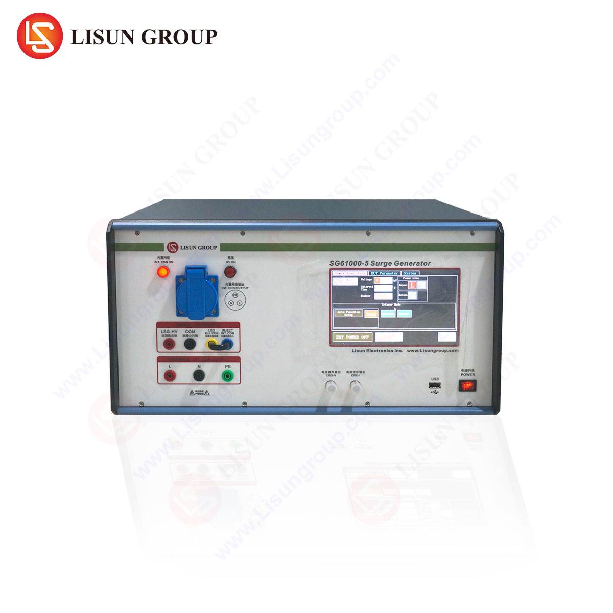
The LISUN SG61000-5 Surge Generator embodies the engineering principles described above, packaged into a robust and user-friendly system designed for compliance with international standards including IEC 61000-4-5. This generator is engineered to evaluate the immunity of equipment against surges originating from switching transients and lightning effects.
Its specifications define its extensive application range. The system can generate an open-circuit output voltage up to 6.0 kV for the combination wave (1.2/50 μs voltage wave with an 8/20 μs current wave) and up to 3.0 kV for the communication wave (10/700 μs). The short-circuit current capability reaches 3.0 kA for the combination wave. The polarity of the output surge can be switched between positive and negative, and the generator offers both manual and automated remote control operation, the latter facilitated via an RS232 or other computer interface for integration into automated test sequences.
The operational principle of the SG61000-5 follows a classic architecture. The internal high-voltage capacitor is charged from a DC source. A triggered spark gap then discharges this stored energy into the wave-shaping network. This network is designed with specific values of resistance and inductance to sculpt the discharge into the required standard waveforms. The generator features separate outputs and internal networks for power port testing (combination wave) and communication/data line testing (combination wave with higher source impedance or the 10/700 μs wave), making it a versatile tool for comprehensive equipment evaluation.
Industry-Specific Applications and Compliance Testing
The application of impulse voltage testing is ubiquitous across industries where electrical reliability is non-negotiable.
In the Lighting Fixtures and Power Equipment sectors, products such as high-bay industrial LEDs, street luminaires, distribution transformers, and insulators are subjected to impulse tests to ensure their insulation can withstand induced lightning surges on power lines, as per IEC 60598-1 and IEC 60076-3.
Household Appliances, Power Tools, and Low-voltage Electrical Appliances are tested to standards like IEC 60335-1 to verify that transient overvoltages from motor commutation or local switching will not cause breakdown or create a fire hazard.
Industrial Equipment, Instrumentation, and Medical Devices must demonstrate immunity to surges coupled into their AC power ports and control lines, ensuring operational continuity and patient safety in accordance with IEC 61000-4-5 and IEC 60601-1-2.
The Automobile Industry and Rail Transit sectors employ surge testing on electronic control units (ECUs), battery management systems, and traction systems to simulate load dump transients and other switching events common in 12V, 24V, and high-voltage vehicle architectures, referencing standards such as ISO 7637-2 and IEC 61000-4-5.
For Communication Transmission, Audio-Video Equipment, Intelligent Equipment, and Information Technology Equipment, testing focuses on data and signal ports. The 10/700 μs wave is particularly relevant here, simulating surges induced on long-distance communication cables, as mandated by standards like ITU-T K.20 and IEC 61000-4-5.
At the component level, manufacturers of Electronic Components such as varistors, gas discharge tubes, and semiconductor devices use systems like the SG61000-5 to characterize the clamping voltage and energy absorption capabilities of their protective components.
Even the extreme environments of Spacecraft and Aerospace require rigorous surge testing for avionics, where equipment must be qualified to withstand specific electromagnetic transient events, ensuring mission-critical systems remain functional.
Advantages of Modern Surge Generator Systems
Modern systems like the LISUN SG61000-5 offer significant advantages over older generations of test equipment. A primary benefit is precision and repeatability. Advanced components and digital control ensure that the generated waveforms consistently meet the tight tolerances required by international standards, which is critical for obtaining valid and reproducible test results.
Operational safety is paramount when dealing with high-energy impulses. These systems incorporate comprehensive safety interlocks, emergency stop mechanisms, and protective earthing to safeguard the operator. Furthermore, user-friendly software interfaces simplify the complex process of setting up test parameters—such as voltage level, wave shape, number of impulses, and repetition rate—reducing the potential for operator error and enhancing testing efficiency.
The flexibility for both manual control and automated computer-controlled operation allows for seamless integration into production line testing and sophisticated R&D laboratory environments. This adaptability, combined with a design focused on compliance with a wide array of international standards, makes a capable surge generator a future-proof investment for any test laboratory serving multiple industries.
Frequently Asked Questions
What is the difference between a Combination Wave and a 10/700μs Communication Wave?
The Combination Wave (1.2/50μs voltage, 8/20μs current) is primarily used for testing power ports and short signal lines, simulating surges from lightning and switching transients on power distribution systems. The 10/700μs wave, with a longer duration, is specifically designed for testing telecommunications and data line ports, simulating the waves that can be induced on long-distance overhead communication cables by lightning strikes.
Why is waveform calibration critical for impulse testing?
The severity of the stress imposed on a device under test is directly related to the precise shape of the impulse voltage and current. If the wavefront time is too fast or too slow, or the energy content (defined by the tail) is incorrect, the test will not accurately simulate a real-world event. This can lead to either over-testing (rejecting good products) or, more dangerously, under-testing (passing products that would fail in the field). Calibration ensures the test is both repeatable and standards-compliant.
How do you select the appropriate test levels for a given product?
Test levels are not arbitrary. They are defined by the product’s intended operating environment and the applicable immunity standard. For example, a medical device for use in a hospital might have a different severity level (e.g., 2 kV line-to-line, 4 kV line-to-earth) than an industrial controller located in a factory with large motors (e.g., 4 kV line-to-line, 6 kV line-to-earth). The product committee defining the standard determines these levels based on environmental studies.
Can the LISUN SG61000-5 be used for both pass/fail testing and component characterization?
Yes, absolutely. In a production environment, it is typically used for pass/fail verification: applying a specified number of impulses at a defined voltage level and monitoring for breakdown. In an R&D or component engineering lab, it is used for characterization: gradually increasing the voltage or energy level to determine the breakdown threshold or energy handling capability of a component or insulation system, providing valuable data for design improvement.
What safety precautions are mandatory when operating a surge generator?
Operation must strictly follow the manufacturer’s guidelines. Essential precautions include: operating the system within a secured test bay with access barriers; ensuring the equipment under test and the generator are properly earthed; using high-voltage warning signs; employing safety interlocks that prevent energization if doors are open; and utilizing a “dead-man” switch or emergency stop that immediately discharges the capacitors in case of an emergency.


