A Comprehensive Guide to Surge Immunity Testing for Electrical and Electronic Equipment
Introduction to Electrical Surge Phenomena
Electrical surges, characterized by transient overvoltages of high amplitude and short duration, represent a significant threat to the operational integrity and longevity of electronic systems. These phenomena originate from both natural sources, such as lightning strikes inducing currents in power distribution networks, and man-made sources, including the switching of heavy inductive loads like industrial motors or power factor correction capacitors. The increasing sophistication and miniaturization of electronic components have concurrently increased their vulnerability to such transient disturbances. Consequently, surge immunity testing has become an indispensable component of the product validation lifecycle, mandated by international standards to ensure that equipment can withstand real-world electrical stress without performance degradation or catastrophic failure.
Fundamental Principles of Surge Waveform Generation
The simulation of surge events in a controlled laboratory environment requires the generation of standardized waveforms that accurately replicate the characteristics of natural and switching transients. The key parameters defining a surge waveform are its rise time, which indicates the speed at which the voltage increases to its peak, and its duration, measured as the time for the voltage to decay to half its peak value. The most critical waveforms, as defined by standards such as IEC 61000-4-5, are the Combination Wave (CW) and the Communication Line Wave (CLW). The Combination Wave is delivered from a generator with a specified source impedance, producing a 1.2/50 μs open-circuit voltage wave and an 8/20 μs short-circuit current wave. This dual characteristic allows for the testing of equipment ports connected to both power mains and relatively long-signal lines. The generation of these precise waveforms is achieved through sophisticated circuitry involving high-voltage capacitors, pulse-forming networks, and triggered spark gaps or solid-state switches, which discharge stored energy into the Equipment Under Test (EUT) in a highly controlled and repeatable manner.
Architectural Overview of the LISUN SG61000-5 Surge Generator
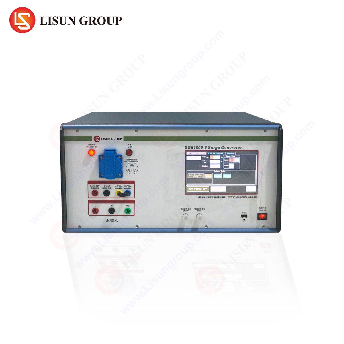
The LISUN SG61000-5 Surge Generator represents a state-of-the-art implementation of surge testing technology, engineered to meet and exceed the rigorous demands of modern compliance testing. Its architecture is designed for precision, flexibility, and user safety. The core of the system is a high-energy capacitor bank that is charged to a pre-set voltage. Upon triggering, this energy is released through a pulse-forming network to shape the output into the required standard waveforms. A key feature of the SG61000-5 is its integrated coupling/decoupling network (CDN), which facilitates the application of surge pulses to the EUT while isolating the surrounding auxiliary equipment and the public mains supply from damaging transient voltages. The system is governed by a microprocessor-based controller, which can be operated via a color touchscreen interface or remotely via PC software, allowing for the programming of complex test sequences, including polarity switching, phase synchronization, and repetition rate control.
Key Specifications of the LISUN SG61000-5:
- Output Voltage: 0.2 – 6.2 kV for Combination Wave (1.2/50 μs – 8/20 μs).
- Output Current: Up to 3.2 kA for Combination Wave.
- Source Impedance: Selectable 2Ω, 12Ω, and 42Ω to simulate different surge environments.
- Polarity: Positive, negative, or alternating, with phase angle selection (0°-360°) for AC power line testing.
- Repetition Rate: Programmable, with a minimum interval of 20 seconds.
- Coupling Modes: Line-to-Line (L-L) and Line-to-Ground (L-G) for both power and signal lines.
- Compliance Standards: Fully complies with IEC 61000-4-5, EN 61000-4-5, and other derivative standards.
Methodology for Surge Test Setup and Execution
Executing a valid and repeatable surge test requires a meticulous setup procedure. The test environment must be properly grounded, and the EUT should be configured in its typical operational state. The test plan, derived from the applicable product standard, defines the test levels, the number of surges, and the ports to be tested.
The initial step involves selecting the appropriate coupling method. For power ports, surges are typically applied in Line-to-Ground mode to assess common-mode immunity, and in Line-to-Line mode for differential-mode stress. The SG61000-5’s integrated CDN simplifies this process. For communication ports, such as Ethernet or telephone lines, a dedicated Communication Line Coupling Network is used to inject the surge while protecting the test system. The test level, expressed in kilovolts (kV), is selected based on the equipment’s intended installation environment—ranging from a protected level 1 (0.5 kV) to a severe level 4 (4 kV).
During execution, a series of surges, typically five positive and five negative at each selected phase angle of the AC power cycle (e.g., 0°, 90°, 180°, 270°), are applied. The EUT is monitored continuously for any degradation of performance or violation of its functional performance criteria, which are classified as:
- Criterion A: Normal performance within specification limits.
- Criterion B: Temporary loss of function or performance which is self-recoverable.
- Criterion C: Temporary loss of function or performance requiring operator intervention or system reset.
- Driterion D: Loss of function or performance which is not recoverable due to damage.
Application of Surge Testing Across Industrial Sectors
The universality of surge threats necessitates their consideration across a vast spectrum of industries.
- Lighting Fixtures: Modern LED drivers and intelligent lighting controllers are highly susceptible to voltage transients. Surge testing ensures that a streetlight or industrial high-bay fixture can withstand a nearby lightning strike without failure.
- Household Appliances and Power Tools: Appliances containing variable-speed drives, such as washing machines or cordless drills, incorporate sensitive power electronics. Testing validates that motor commutation and control logic remain stable during common power grid disturbances.
- Medical Devices: For patient-connected equipment like ventilators or dialysis machines, functional safety is paramount. Surge immunity is critical to prevent malfunctions that could endanger patient lives, especially for devices used in a home-care environment with less stable power.
- Automotive Industry and Rail Transit: Vehicles are exposed to complex electromagnetic environments, including load-dump transients from the alternator and inductive load switching. Testing according to standards like ISO 7637-2 (using appropriate wave shapes) ensures the reliability of engine control units, infotainment systems, and critical safety electronics.
- Information Technology and Communication Transmission: Data centers and telecom base stations are primary targets for lightning-induced surges. Testing routers, servers, and network switches guarantees data integrity and network availability.
- Aerospace and Spacecraft: In these sectors, reliability is non-negotiable. Surge testing is applied to avionics, power distribution units, and ground support equipment to withstand transients from auxiliary power unit start-up or static discharge.
- Instrumentation and Industrial Equipment: Precision measurement instruments and programmable logic controllers (PLCs) used in factory automation must operate flawlessly in electrically noisy environments dominated by large motor drives and solenoids.
Comparative Analysis of Surge Generator Capabilities
When evaluating surge generators, several technical differentiators separate basic compliance tools from advanced engineering instruments like the LISUN SG61000-5. A primary factor is waveform accuracy and consistency. The SG61000-5 utilizes precision components and a stable triggering mechanism to ensure that each surge pulse conforms to the tolerances outlined in IEC 61000-4-5, which is critical for generating reliable and reproducible test data.
Operational flexibility is another key differentiator. The ability to seamlessly switch between source impedances (2Ω for current-heavy Line-to-Line coupling, 12Ω for standard Line-to-Ground, and 42Ω for long-distance signal lines) within a single instrument eliminates the need for external adapters and reduces setup time. Furthermore, the generator’s high-current capability of 3.2 kA future-proofs the investment, allowing it to test not only standard consumer products but also robust industrial and power equipment that may be subjected to more severe surge conditions. The integrated, software-controlled CDN provides a significant advantage over systems with separate components, reducing wiring errors and enhancing overall test efficiency and safety.
Interpreting Test Results and Failure Analysis
A successful test concludes with the EUT meeting its specified performance criteria (typically A or B). However, a failure (Criterion C or D) necessitates a systematic root-cause analysis. The first step is to identify the failure mode—whether it was a hard failure (catastrophic component damage like a exploded varistor or shorted semiconductor) or a soft failure (system lock-up or data corruption).
Common points of failure include:
- Transient Voltage Suppression (TVS) Diodes: Overstressed beyond their peak pulse power rating.
- Varistors: Degraded or cracked due to energy absorption beyond their capability.
- Capacitors: Dielectric breakdown, particularly in Y-capacitors used for EMI filtering.
- PCB Traces: Fusing or delamination caused by excessive current density.
- Galvanic Isolation: Breakdown in optocouplers or isolation transformers.
Using the SG61000-5’s capability to precisely control test levels, an engineer can perform a “step-stress” test, gradually increasing the surge voltage to identify the exact threshold of failure. This data is invaluable for redesigning protection circuits, improving PCB layout to reduce parasitic inductances, or selecting more robust components, ultimately leading to a more reliable product.
Integrating Surge Testing into a Broader EMC Validation Strategy
Surge immunity testing is not an isolated activity but a critical component of a comprehensive Electromagnetic Compatibility (EMC) validation strategy. It is intrinsically linked to other immunity tests. For instance, a product that fails Electrical Fast Transient (EFT) testing may also exhibit vulnerabilities at higher energy surges, as both often stress similar input protection circuits. Conversely, a well-designed surge protection circuit will often also improve performance against EFT and Electrostatic Discharge (ESD).
A robust validation strategy sequences these tests logically. Typically, lower-energy, high-repetition tests like EFT are performed before high-energy surge tests. This approach helps identify weak points without immediately causing destructive failures. The data from surge testing informs the design lifecycle, feeding back into the prototyping phase to create products that are inherently robust from their first iteration, thereby reducing development time and cost.
Frequently Asked Questions (FAQ)
Q1: What is the significance of the phase angle selection feature in the SG61000-5?
The phase angle selection allows the surge to be injected at a specific point on the AC power sine wave. This is critical for testing equipment with switching power supplies, as the surge’s impact can vary dramatically depending on whether it occurs at the zero-crossing or at the peak of the voltage waveform. Testing at multiple phase angles (e.g., 0°, 90°, 180°, 270°) ensures comprehensive coverage and uncovers potential vulnerabilities that might be missed with random phase application.
Q2: How does the selectable source impedance (2Ω, 12Ω, 42Ω) affect the test?
The source impedance determines the current delivered to the EUT for a given voltage setting. A 2Ω impedance simulates a low-impedance source, such as a direct lightning stroke on a nearby power line, resulting in very high current (e.g., 3.1 kA at 6.2 kV). The 12Ω impedance represents the standard impedance of a building’s electrical wiring. The 42Ω impedance is used for testing long-distance communication or signal lines, where the line resistance limits the current. Selecting the correct impedance is essential for simulating a realistic threat environment.
Q3: Our product standard requires testing on both power and communication ports. Does the SG61000-5 support this?
Yes. The LISUN SG61000-5 is a comprehensive system. Its main unit includes the coupling/decoupling networks for single- and three-phase power ports. For communication ports such as RS-232, RS-485, Ethernet (RJ45), or telephone (RJ11), LISUN offers a range of auxiliary Communication Line Coupling Networks (CLCN) that connect directly to the main generator. These CLCNs are designed to safely inject the surge onto the data lines while providing high-frequency isolation to protect the generator and other auxiliary equipment.
Q4: What are the primary safety precautions when operating a high-energy surge generator?
Safety is paramount. Key precautions include: ensuring the unit and the EUT are properly connected to a reliable earth ground; using only high-voltage rated cables and connectors; establishing a clear safety perimeter around the test setup; using the instrument’s remote trigger capability to maintain a safe distance during surge application; and fully discharging the internal capacitors before making any connections or adjustments to the EUT or test setup. The SG61000-5 incorporates multiple safety interlocks and discharge circuits to mitigate risks.


